
Courtesy: Gopinathan P, Calicut, India
Biomechanics of the Hip: Core Principles, Lever Systems, and Clinical Applications
Core Takeaways
-
Intrinsic Stability: Unlike the knee, the hip is a highly congruent ball and socket joint functioning as a Class 1 first order lever system.
-
Load Multipliers: Single leg stance multiplies joint reactive forces up to 3 to 4 times body weight due to the required abductor muscle counter pull across an asymmetric lever arm.
-
Biomechanical Symmetry: Preservation of femoral offset, abductor lever arm length, and the anatomical mechanical axis relationship governs long term success in fracture fixation and total hip arthroplasty.
Lower Limb Alignment and Axes
-
Mechanical Axis: A straight line drawn from the center of the femoral head to the center of the ankle talocrural joint.
-
Anatomical Axis: A mid diaphyseal line traversing the center of the femoral shaft knee up toward the tip of the greater trochanter.
-
Physiological Divergence: The anatomical and mechanical axes intersect at the knee forming a physiological angle of approximately 5 to 7 degrees of valgus.
-
Clinical Significance: Disruption of this angular relationship alters load distribution through the knee and hip.
Lever Mechanics and Force Transmission
-
Class 1 Lever Model:
-
Fulcrum: Center of rotation of the femoral head.
-
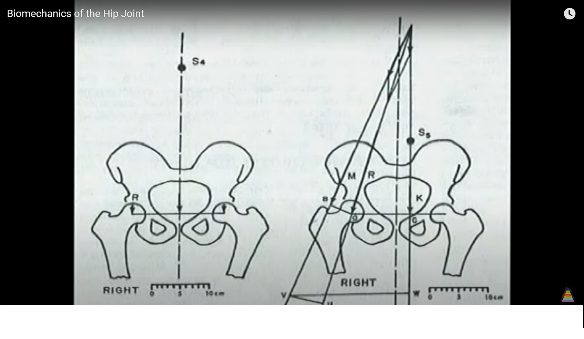
Load Arm Body Weight: Distance from the center of gravity sacrum midline to the femoral head center.
-
Effort Arm Abductor Vector: Distance from the femoral head center to the lateral footprint of the greater trochanter femoral offset.
-
-
Static Bilateral Stance: Body weight is divided symmetrically across both femoral heads, approximately 0.5 times body weight per hip.
-
Single Leg Stance Trendelenburg State:
-
When the contralateral leg leaves the ground, the center of gravity exerts an adduction moment that causes the unsupported pelvis to drop.
-
To stabilize the pelvis horizontally, the abductor musculature gluteus medius and minimus must contract with high force.
-
-
Mechanical Advantage Disparity: The ratio of the body lever arm to the abductor lever arm is approximately 3 to 1.
-
Joint Reaction Force:
-
The hip fulcrum experiences the algebraic summation of body weight plus the required abductor contractile force.
-
Joint reaction force equals body weight plus abductor force, which totals approximately 3 to 4 times body weight.
-
Force climbs even higher during dynamic activities such as stair ascent.
-
Cane Biomechanics and Load Alleviation
-
Contralateral Placement: A cane must be held in the hand opposite to the affected weight bearing hip.
-
Mechanical Counter Torque: Pushing down on a contralateral cane creates a long counter torque lever arm that assists the abductor muscles in preventing pelvic drop.
-
Magnitude of Relief: Transmitting merely 15 percent of body weight through an upper limb contralateral cane reduces the joint reaction force acting across the stance hip by roughly 50 percent.
-
Muscle Preservation: Substantially lessens the contractile force demand placed on the ipsilateral gluteus medius.
Weight Transmission Vector and Sagittal Gait Dynamics
-
Stable Static Vector: The normal line of weight transmission falls posterior to the center of rotation of the hip and anterior to the flexion axis of the knee, locking joints in place with minimal active muscular energy expenditure.
-
Malalignment Risks: An excessively anterior weight line precipitates posterior pelvic collapse instability, whereas an excessively posterior line forces forward pitch.
-
Heel Strike Phase: The weight vector is positioned anteriorly as the pelvis rotates forward.
-
Mid Stance Phase: The vector transitions posteriorly as the pelvis rotates backward to maintain smooth progression of the center of mass.
Angular Deformities: Coxa Valga vs Coxa Vara
| Biomechanical Parameter | Coxa Valga (Greater than 135 degrees) | Coxa Vara (Less than 120 degrees) |
| Neck Shaft Angle | Increased | Decreased |
| Abductor Lever Arm Offset | Shortened or Decreased | Lengthened or Increased |
| Abductor Force Demand | Drastically increased with less mechanical advantage | Mechanically optimized but muscles can become functionally slackened |
| Joint Reaction Force | Markedly elevated up to 7 times body weight | Decreased overall compressive burden |
| Dominant Physical Stress | Excessive joint contact compression and cartilage wear | High bending and shearing forces across the femoral neck |
| Clinical Presentation | Early fatigue and progressive arthrosis | Risk of fatigue failure, varus collapse, and Trendelenburg lurch |
Applied Biomechanics in Arthroplasty
-
Femoral Offset and Trochanteric Height: A line drawn across the tip of the greater trochanter should align closely with the center of rotation of the femoral head. Placing the head center far above or below the trochanteric tip disrupts resting abductor tension, leading to limp or chronic impingement.
-
Excessive Cup Inclination: Greater than 45 degrees reduces acetabular coverage, elevates edge loading stress, and causes component dislocation.
-
Stem Placement in Varus: Focuses excessive tensile and shear stress along the proximal lateral and distal medial cement bone mantle, risking early aseptic loosening and periprosthetic stem fracture.
-
Iatrogenic Limb Lengthening: Overtightens the myofascial envelope, elevating baseline resting compressive joint reaction forces.
Applied Biomechanics in Femoral Neck Fractures
-
Valgus Impacted Fractures: Subjected to favorable compressive impaction lines that reliably promote secondary osseous union. However, severe valgus can alter proximal femoral geometry, elevating articular contact stresses that increase the risk of late femoral head avascular necrosis.
-
Pauwels Angle Classification:
-
Type I: Less than 30 degrees to the horizontal plane with dominant compressive vectors; stable.
-
Type II: 30 to 50 degrees to the horizontal plane; intermediate stability.
-
Type III: Greater than 50 degrees to the horizontal plane; vertical shear fracture pattern.
-
-
Pauwels Type III Mechanics and Realignment:
-
High vertical angles generate destructive shear stresses at the fracture interface, preventing union and causing hardware cutout.
-
A valgus producing intertrochanteric abduction osteotomy converts the vertically oriented Pauwels Type III fracture plane into a more horizontal Pauwels Type I orientation.
-
This orientation shift converts disruptive shearing forces into stable axial compression to promote reliable union.
-
nice presentation